WaveLink
WaveLink
WaveLink
Select OEM-Grade Interface Components Ready for Global Export and System Integration
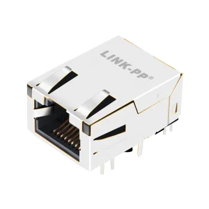
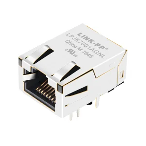
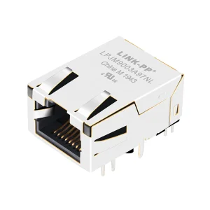
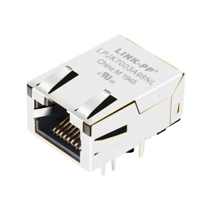
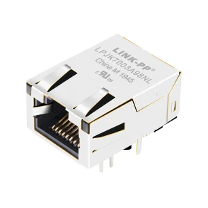
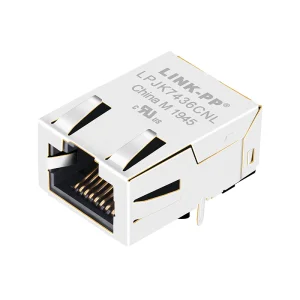
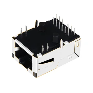
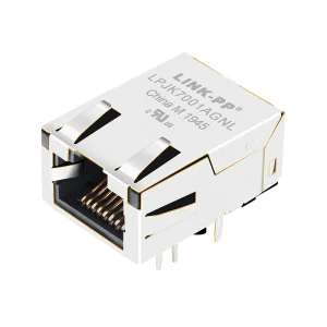
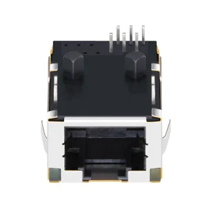
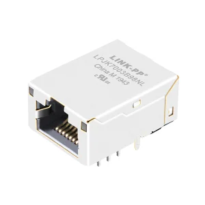
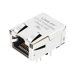
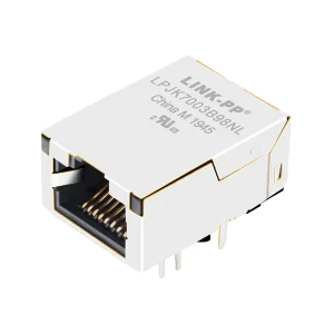
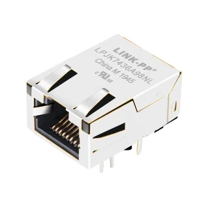
As microelectronics design advances towards absolute space optimization, standard-height RJ45 modular jacks present physical limitations for multi-layered system architectures. In dense server blades, slim IoT gateways, and sub-1U rack mount structures, the z-axis headroom is heavily restricted. The global procurement demands for low profile RJ45 female connectors are powered by four critical variables: spatial compactness, structural reliability, electromagnetic compatibility (EMC), and high-frequency thermal dispersion.
Selecting the correct low profile mechanical interface is no longer a trivial consideration. Standard modular jacks exceed a height profile of 16mm to 18mm, making them incompatible with compact PCB topologies. High-quality low-profile alternatives compress this vertical footprint to less than 11.5mm. This spatial adjustment facilitates dense board-to-board stackings and improves volumetric efficiency within modular hardware clusters. By minimizing structural heights, network engineering teams can maximize component placement on dual-sided PCBs and enable optimal airflow pathways in passive cooling enclosures.
Furthermore, structural reliability remains non-negotiable for enterprise networks. When vertical profiles are reduced, mechanical tolerance margins narrow significantly. Connectors must withstand standard insertion and extraction forces without micro-fracturing structural solder joints or degrading physical contact surfaces. WaveLink's advanced housing geometries use liquid crystal polymers (LCP) capable of resisting extreme reflow thermal curves, ensuring long-term mechanical reliability under aggressive insertion cycles.
Your Trusted Strategic B2B ODM/OEM Integration Partner for Next-Gen Fiber & Copper Connectivity Solutions
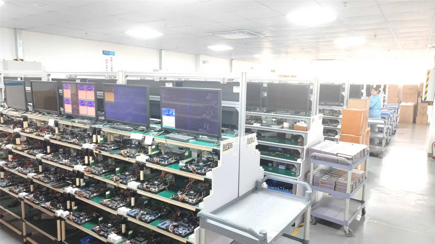


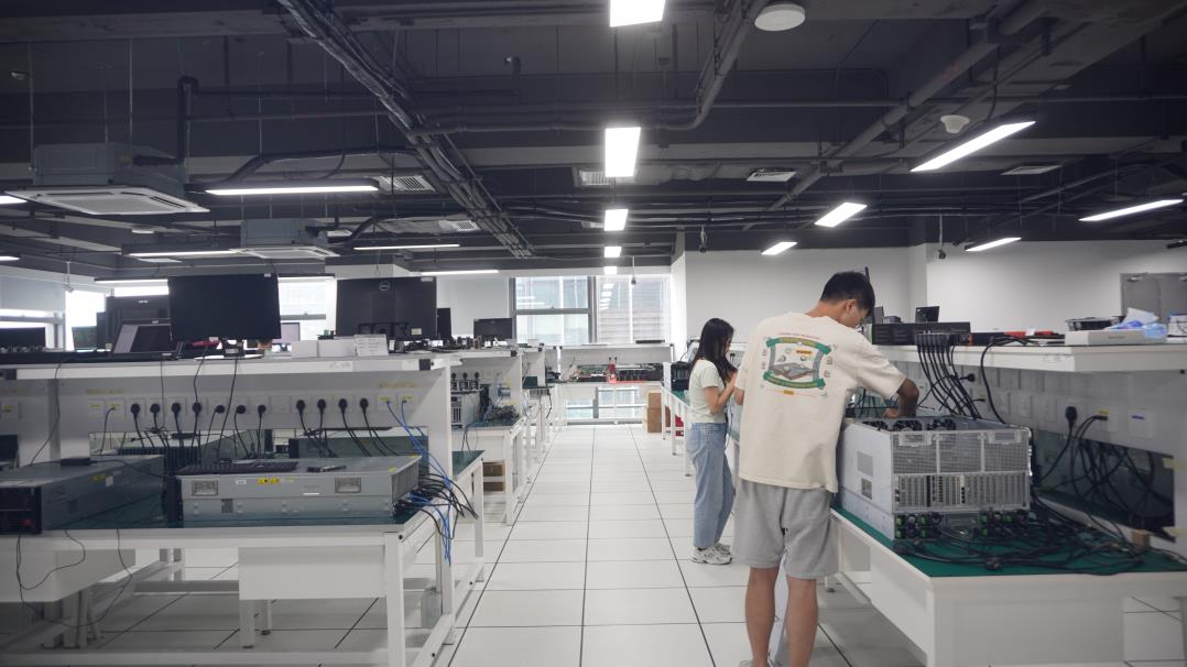
Founded in 2016, WaveLink Optoelectronics Co., Ltd. has established a strong presence in the global B2B optoelectronics and connectivity industry, drawing on over 12 years of core industry expertise. Our production facility is equipped to handle custom design and high-volume manufacturing demands.
Quality assurance is integral to our manufacturing processes. WaveLink implements a comprehensive quality management system that includes 100% mechanical performance validation, optical signal integrity checks, and high-temperature aging tests. Our physical inspection methods integrate automated optical testing (AOI), manual visual examination, and real-time digital calibration systems, overseen by 45 dedicated QC engineers to maintain production consistency.
Supported by a network of over 1,200 supply chain partners, we ensure reliable component sourcing and production scalability. WaveLink supports global B2B partners through customized engineering, OEM/ODM solutions, and protocol-specific optimizations, having introduced approximately 180 new product models in the past year alone.
Understanding the electrical layout, physical shielding, and signal path characteristics of low-profile Ethernet interfaces.
| Functional Parameter | Integrated Magnetic Low-Profile RJ45 (Magjack) | Discrete Non-Magnetic Low-Profile RJ45 |
|---|---|---|
| Spatial Footprint | Combines the connector and magnetics into a single, compact housing to conserve PCB area. | Requires external magnetic modules on the motherboard, taking up additional space. |
| EMI & ESD Shielding | Includes 360° copper shielding with integrated panel ground tabs to control electromagnetic noise. | Requires external shielding solutions and careful PCB path planning. |
| Signal Integrity (insertion loss) | Optimized internal wiring paths help control insertion loss and improve return loss parameters. | Dependent on physical trace layout between the discrete connector and magnetics. |
| Speed Capability | Available in variants supporting 10/100M, 1G, 2.5G, 5G, and 10G Base-T speeds. | Configurable to support various speeds based on the external PHY and magnetic module specs. |
| Thermal Behavior | Requires adequate airflow design to manage thermal accumulation in high-speed, multi-gigabit setups. | Distributes heat generation across multiple separate components on the PCB surface. |
For industrial and high-reliability telecom installations, low profile RJ45 female connectors require specific material properties to withstand demanding environments. The plastic housing must utilize high-temperature thermoplastic resin (UL94 V-0 flammability class rating) such as glass-filled LCP or Nylon 46. Contact pins are typically engineered with high-strength phosphor bronze alloys, plated with a minimum of 50 micro-inches of hard gold over 50-100 micro-inches of nickel underplating. This design maintains low contact resistance (typically under 20 mΩ max change over lifetime) and prevents fretting corrosion from mechanical micro-vibrations.
The shielding shield itself is typically fabricated from tin-plated or nickel-plated brass alloys, featuring multiple grounding tabs that establish contact with the chassis or panel bezel. This configuration forms a Faraday cage around the signal contacts, protecting the differential data channels from high-frequency electromagnetic fields generated by neighboring components, such as switching power units and high-speed CPU arrays.
How low-profile connectivity interfaces support high-performance industrial and telecom platforms globally.
High-density computing servers and accelerator clusters utilize low-profile connectors to maximize backplane space, facilitating greater port density and optimal system airflow.
Outdoor small cells and active antenna arrays rely on compact, low-profile designs that integrate environmental sealing and robust EMI shielding within confined chassis designs.
Embedded computing boards, rugged DIN-rail controllers, and process automation hardware require low-profile connectors that maintain stable, vibration-resistant connections.
The future development of low profile RJ45 female connectors focuses on higher data rates and improved power delivery profiles. We are tracking a clear technological trend toward supporting 10G Base-T speeds in ultra-low profiles, while accommodating high levels of Power over Ethernet (PoE++ Type 4 up to 90W/100W under IEEE 802.3bt specifications).
Managing up to 100W of electrical energy within a low-profile connector requires careful thermal design. Solder contact resistance and internal layout geometry must be engineered to prevent localized thermal hot spots that could damage LCP housings. Designers are also integrating transient voltage suppression (TVS) diodes directly within the shielding structures of the RJ45 unit, improving transient protection for sensitive downstream PHY chips.
To access tier-1 global equipment programs, low-profile connectors must comply with international testing and environmental directives. WaveLink products comply with RoHS and REACH regulations to restrict hazardous substances. Key design practices verify physical contact geometries against FCC Part 68 Subpart F and IEC 60603-7 specifications, helping maintain dimensional consistency across mating plugs.
For critical applications, connectors undergo testing to verify compliance with UL 1863 safety standards and UL 94 V-0 flammability ratings. This supports safe and reliable operation in telecommunications, computing, and industrial hardware environments.
Detailed answers to common engineering, procurement, and deployment questions regarding low-profile connectors.
Low-profile RJ45 female connectors feature a reduced physical height, typically measuring less than 11.5mm to 13.5mm from the PCB surface. In comparison, standard RJ45 connectors average 16mm to 18mm in height. This lower profile helps save space in dense network hardware designs, such as 1U/0.5U server systems, optical transmission modules, and compact IoT devices.
Yes, specialized designs with integrated high-frequency magnetics can support 10G Base-T networks. Achieving 10 Gbps speeds in a compact profile requires careful isolation of internal differential pairs to minimize crosstalk (NEXT/FEXT) and maintain stable signal integrity across the designated frequency band.
Integrated magnetics house the isolation transformer and common-mode choke coils inside the connector shield. This helps conserve PCB real estate, simplifies layout design, and improves EMI performance by locating the magnetic components close to the RJ45 port.
For surface mount technology (SMT) and wave soldering processes, components must use high-temperature plastic materials such as LCP or Nylon 46 (rated UL94 V-0). These materials are designed to tolerate reflow profiles with peak temperatures of 260°C without deformation or mechanical failure.
For telecommunications and industrial equipment, a contact plating of 50 micro-inches of gold over nickel is standard. This thickness provides corrosion resistance and wear protection, helping the connector withstand a minimum of 750 insertion cycles without signal degradation.
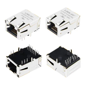
Generally no. Tab-up and tab-down configurations feature different PCB pin layouts and mechanical dimensions. Swapping between them requires revising the PCB footprint and trace routing. Engineers should select the appropriate orientation during the initial board layout phase.
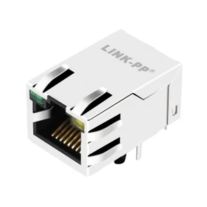
High-integrity interfaces with integrated LEDs and advanced noise-attenuating magnetics.