 WaveLink
WaveLink
WaveLink
Engineered for extreme environments, precision digital calibration, and low signal loss configurations
In modern telecommunication networks, the passive splitting of optical power is essential for expanding broadband reach efficiently. A fiber optic splitter (otherwise known as a beam splitter or optical splitter) takes a single optical signal and divides it into multiple paths. This function forms the basis of Passive Optical Networks (PON), including GPON, EPON, and next-generation 10G-PON/XGS-PON architectures.
As remote work, cloud migration, and IoT systems increase global demand for bandwidth, telecommunications networks must become more dense. Optical splitters provide a cost-effective alternative to run individual home-run fibers from central offices to subscribers. Instead, network designers use a 1:N or 2:N optical division strategy to maximize physical plant capacity. The efficiency of a PON relies on these passive optical splitters performing reliably under varying physical conditions.
Utilizes photolithographic techniques to etch optical waveguides onto a silica glass substrate, ensuring consistent division up to 64 or 128 channels with low insertion loss.
Formed by fusing and stretching two or more fibers together under heat. FBT splitters are ideal for simpler configurations (1x2, 2x2) and customized splitting ratios.
Minimizing Polarization Dependent Loss (PDL) and maintaining a uniform channel distribution prevents errors in high-speed optical data links.
Selecting between Planar Lightwave Circuit (PLC) splitters and Fused Biconical Taper (FBT) splitters depends on the physical network layout, required splitting ratios, operating wavelengths, and environmental factors. The table below outlines the structural differences between these two technologies.
| Performance Parameters | PLC Splitter (Waveguide Chip-Based) | FBT Splitter (Fused Fiber-Based) |
|---|---|---|
| Operating Wavelength Range | Wide spectrum: 1260 nm to 1650 nm (covers O, E, S, C, L bands) | Limited to specific window bands (850nm, 1310nm, 1550nm) |
| Split Ratios | Equal division: 1x4, 1x8, 1x16, 1x32, 1x64, 2x32, 2x64 | Customized splitting configurations (e.g., 90/10, 70/30, 1x2, 2x2) |
| Spectral Uniformity | Highly uniform (typically ≤ 0.8 dB variation across channels) | Varies based on split ratio; lower uniformity at higher splits |
| Polarization Dependent Loss (PDL) | Very low (≤ 0.2 dB to 0.4 dB), preventing polarization fading | Higher variability; dependent on coupling length and tapers |
| Thermal Stability | Excellent (-40°C to +85°C operating temperature) | Moderate; sensitive to thermal expansion/contraction |
| Production Capacity & Scaling | Highly scalable through automated semiconductor packaging | Labor-intensive manual alignment and glass drawing processes |
Note for Network Architects: While FBT splitters are a cost-effective option for simple, asymmetrical 1x2 applications, PLC technology is recommended for multi-dwelling units (MDUs) and GPON/XGS-PON distributions to prevent signal degradation and maintain uniformity across all fiber branches.
Industrial-Scale Fiber Optic Interconnect & Optical Transceiver Manufacturing
Founded in 2016, WaveLink has built a reputation in the global optoelectronics industry as a professional manufacturer specializing in high-performance optical transceivers and fiber optic connectivity solutions for telecom and data center applications. Operating a modern production base covering approximately 12,800㎡, the company manages an annual export revenue of around USD 18 million, supported by 7 years of export experience and 12 years of overall industry expertise.
WaveLink maintains partnerships with more than 1,200 upstream supply chain partners, enabling stable component sourcing and fast production scaling. Its customer base includes telecom operators, data center providers, cloud service companies, and network equipment integrators. Demonstrating strong R&D capability, WaveLink offers custom engineering support, OEM/ODM services, and protocol-specific design optimization options. In the past year alone, the company launched approximately 180 new product models, supported by a research team of around 220 engineers, driving innovation in high-speed optical communication technologies.
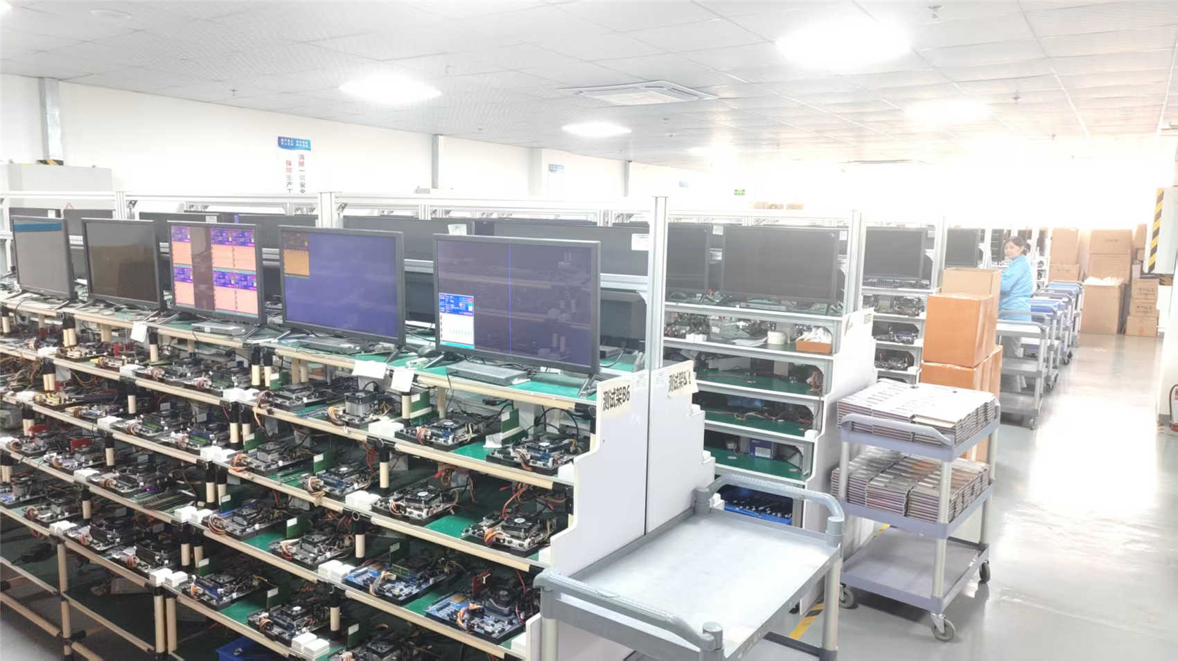
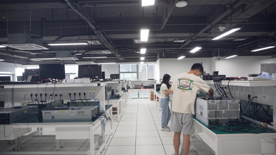
WaveLink operates a strict quality management system, including 100% performance testing, optical signal integrity testing, and high-temperature aging tests. Product inspection methods include automated optical testing, manual visual inspection, and real-time digital calibration systems. The quality control team consists of 45 dedicated QC engineers ensuring product stability and compliance with international standards. Below is an inside look at our assembly lines, cleaning facilities, and testing environments:


Sourcing optical passive components from Chinese manufacturers offers benefits beyond lower labor costs. The primary advantage lies in the integration of the supply chain ecosystem. Within Chinese optoelectronic manufacturing clusters, raw materials such as silica chips, V-grooves, high-precision fiber arrays, and custom packaging boxes are sourced from local tier-1 suppliers, reducing transit times and inventory costs.
This localized supply chain allows manufacturers like WaveLink to scale production quickly when required. For instance, when a global telecommunications provider schedules a regional FTTH rollout, production facilities in China can adjust capacity by drawing on local raw material reserves. This allows for lead times of 1-2 weeks on standard PLC splitters, compared to the 6-8 weeks typical in less integrated manufacturing zones.
Additionally, automated manufacturing processes—such as high-speed robotic chip alignment, UV curing ovens, and multi-port automated optical testing benches—increase production yields. This automation reduces manual intervention and minimizes human error, resulting in consistent optical parameters and long-term field reliability.
Passive optical splitters are deployed across various network architectures, each demanding specific physical configurations to balance space, protection, and accessibility:
When selecting a China wholesale fiber optic splitter manufacturer, procurement departments should verify several technical parameters to ensure compliance with local optical budgets:
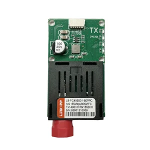
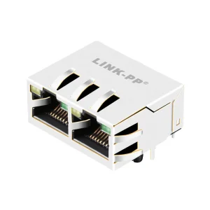
Explore our full catalog of optical communication products designed for carrier-grade applications
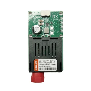
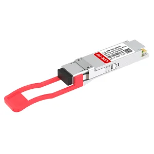
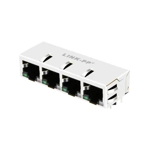
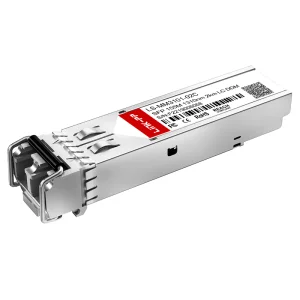
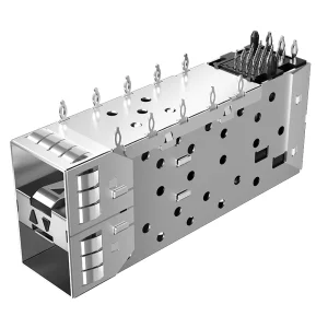
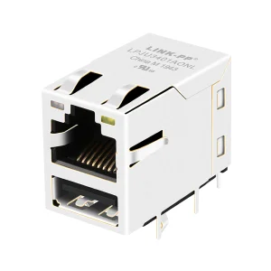
Technical information to assist network engineering departments and purchasing managers