WaveLink
Choosing the right CWDM transceiver can determine whether a fiber link feels stable or becomes a daily troubleshooting task. In real deployments, distance, wavelength, connector type, optical budget, and switch compatibility matter more than attractive product photos. A module that performs well in a laboratory may behave differently inside a warm rack with dusty connectors and long patch cables.
This guide examines five CWDM transceivers for fiber networks. The comparison focuses on practical specifications, including transmission distance, data rate, wavelength options, DOM support, temperature range, and digital compatibility. It also considers vendor documentation, warranty coverage, coding options, and field feedback. These details help network engineers select modules for data centers, campus links, access networks, and metropolitan connections.
There is no universal “best” option. That label depends on the equipment already installed and the network’s optical loss budget. A lower-cost module may be suitable for a short, controlled link. A certified unit may be safer for a critical connection. I have also found that published distance claims need careful review, especially when fiber aging, bends, and connector loss are ignored. Small oversights matter. The following five models offer different balances of reliability, cost, compatibility, and deployment flexibility. Their strengths are clear, but each choice still deserves testing with the actual switch, fiber path, and operating environment.
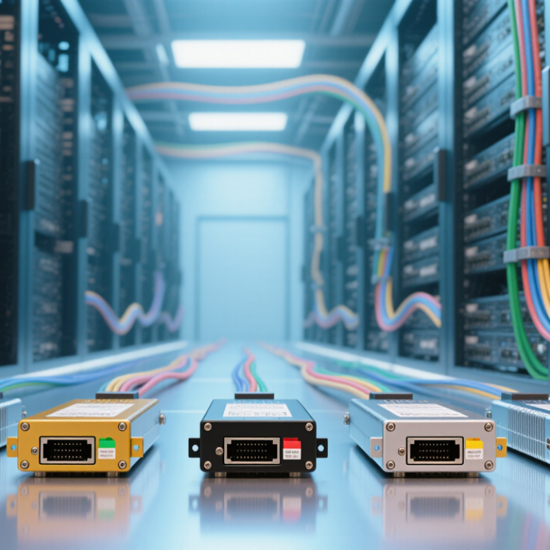
CWDM transceivers are optical modules that carry several data channels through one fiber pair. Each channel uses a different wavelength, usually spaced 20 nanometers apart. A transceiver changes electrical signals into light, then converts received light back into data. Simple in principle.
Inside a CWDM link, a multiplexer combines separate wavelengths at the transmitting site. A demultiplexer separates them at the receiving site. Common systems use wavelengths from about 1270 to 1610 nanometers. This arrangement can support network expansion without installing new fiber cables. Five practical choices may include 1G, 10G, extended-reach, industrial-temperature, and diagnostic-enabled transceivers. The right option depends on speed, distance, fiber loss, and equipment compatibility.
Installation experience shows that specifications deserve careful checking. A module may match the data rate but use the wrong wavelength or connector. That mistake can leave a link dark. Check the optical budget, transmission distance, operating temperature, and duplex requirements before purchasing. Digital monitoring can reveal power levels and temperature during maintenance. It helps.
CWDM also has limits. Channel spacing is wider than dense WDM, but total capacity remains finite. Long links may need amplification or better loss planning. I have seen teams focus on speed and overlook aging patch panels. That is an easy error. Clean connectors, accurate wavelength pairing, and verified compatibility often matter more than impressive headline performance.
The five best CWDM transceivers are not chosen by price alone. They must match the network’s wavelength plan, fiber type, reach, and equipment ports. A practical selection starts with accurate wavelength spacing. Common CWDM channels use the 1270–1610 nm range, but available optical budgets differ between models.
Reach matters in real installations. A short campus link may need only 10 kilometers, while a regional connection can require 40 kilometers or more. Check transmitter power, receiver sensitivity, and connector polish together. A higher advertised distance can become unreliable after patch panels, bends, and aging splices. Small losses add up.
Digital optical monitoring is another valuable feature. It can report temperature, voltage, bias current, and received power before a link fails. I also look for low power consumption and a broad operating temperature range, especially inside crowded cabinets. Industrial-rated units usually handle uneven conditions better. Compatibility deserves careful testing. Confirm the data rate, fiber mode, port encoding, and management support with the existing switch or router. Vendor coding restrictions can also complicate replacement planning. I once saw a technically suitable module rejected because its monitoring data was incomplete. That detail was easy to miss. A dependable CWDM transceiver should offer stable performance, clear diagnostics, documented compliance, and a realistic optical budget rather than impressive figures alone.
| Rank | Recommended CWDM Transceiver | Typical Data Rate | Common CWDM Wavelengths | Typical Transmission Distance | Fiber Type | Optical Connector | Common Form Factor | Key Features | Best-Fit Network Application |
|---|---|---|---|---|---|---|---|---|---|
| 1 | 1G CWDM Ethernet Transceiver | 1.25 Gb/s Ethernet | 1271, 1291, 1311, 1331, 1351, 1371, 1391, 1411, 1431, 1451, 1471, 1491, 1511, 1531, 1551 or 1571 nm | Up to 40 km, depending on optical power and link budget | Single-mode fiber, typically OS2 | Duplex LC | SFP | Cost-effective deployment, digital optical monitoring on many versions, and broad compatibility with 1G Ethernet equipment | Campus networks, access aggregation, and low-cost point-to-point links |
| 2 | 10G CWDM Short-Reach Transceiver | 10.3125 Gb/s Ethernet | 1271-1611 nm CWDM channel plan, selected according to the network design | Up to 10 km in typical single-mode deployments | Single-mode fiber, typically OS2 | Duplex LC | SFP+ | Low power consumption, compact hot-pluggable design, and support for standard 10GbE interfaces | Enterprise buildings, metropolitan access links, and short data-center interconnects |
| 3 | 10G CWDM Medium-Reach Transceiver | 10.3125 Gb/s Ethernet | 1271-1611 nm CWDM channel plan, with one wavelength assigned per optical channel | Up to 40 km under a suitable link budget | Single-mode fiber, typically OS2 | Duplex LC | SFP+ | Higher optical output than short-reach versions, wavelength-division multiplexing, and reliable operation over regional fiber routes | Metropolitan-area networks, service-provider aggregation, and inter-building connections |
| 4 | 10G CWDM Long-Reach Transceiver | 10.3125 Gb/s Ethernet | 1271-1611 nm CWDM channel plan, subject to the selected optical channel | Up to 80 km with an appropriate optical budget and low-loss fiber path | Single-mode fiber, typically OS2 | Duplex LC | SFP+ | Extended reach, stronger transmit optics, receiver sensitivity requirements, and careful loss and dispersion planning | Long metropolitan links, regional aggregation, and remote-site connectivity |
| 5 | 25G CWDM Ethernet Transceiver | 25.78 Gb/s Ethernet | 1271, 1291, 1311, 1331, 1351, 1371, 1391 or 1411 nm; exact channels depend on the optical design | Typically up to 10 km | Single-mode fiber, typically OS2 | Duplex LC | SFP28 | Higher port density and throughput than 10G, low-latency optical connectivity, and support for modern server and switch uplinks | Data-center interconnects, 5G transport, and high-capacity access networks |
Five Leading CWDM Transceivers for Fiber Network Applications
CWDM transceivers extend fiber capacity without installing new cable. The ITU Facts and Figures 2023 report counted 5.4 billion people online worldwide. OECD Broadband Statistics also showed fiber represented about 42% of fixed broadband connections in 2023. These figures reinforce the need for practical, scalable optical links.
The leading choices include 1G SFP modules for campus access, 10G SFP+ units for aggregation, and 25G SFP28 modules for modern server connections. Forty-gigabit QSFP+ transceivers suit older data-center backbones. One-hundred-gigabit QSFP28 models support high-density uplinks across metropolitan networks. Each option should match distance, wavelength, connector type, and switch compatibility.
Measure first. A field installation can look healthy while suffering from excessive optical loss. Power readings, connector cleanliness, and dispersion limits deserve careful checks. CWDM is not always the best answer for rapidly growing traffic. A 25G link may be cheaper today, yet a 100G design could reduce future maintenance. The ranking is therefore practical, not absolute. Some networks still overbuy capacity, while others underestimate cooling and patch-panel space. Use the report data as context, not as a substitute for link-budget testing.
Comparison of representative CWDM transceiver configurations by maximum single-mode fiber reach.
CWDM transceivers use separate wavelength channels, typically spaced 20 nm apart across the 1270–1610 nm range. The chart shows common industry configurations for data-center interconnects, metro access, and enterprise fiber links. Actual transmission distance depends on fiber attenuation, connector loss, dispersion, optical power budget, and the selected wavelength.
CWDM transceivers remain practical where fiber capacity must grow without installing new cables. ITU-T G.694.2 defines 20 nm channel spacing across the coarse wavelength range. That spacing supports simpler filters and lower operating costs than dense wavelength systems. Cisco’s Annual Internet Report forecast global IP traffic at 396 exabytes per month in 2022. This pressure makes affordable wavelength upgrades more relevant.
The five strongest choices serve different network conditions. A 1G module offers the lowest entry cost for access links. A 10G module usually provides the best balance for enterprise aggregation. A 25G module suits modern data-center uplinks, but its value depends on switch support and fiber quality. An extended-reach version helps span longer campus routes, where optical loss becomes visible. An industrial-temperature module adds stability in roadside cabinets and unconditioned rooms.
Performance is not only about headline speed. Field testing should check received power, dispersion limits, digital diagnostics, and connector cleanliness. LightCounting’s 2024 optical market analysis reports continuing investment in higher-speed networking, yet many networks still operate below maximum port capacity. That gap can favor CWDM. However, cheap optics may create unstable links when temperature changes. I have seen a link pass daytime tests and fail overnight. That result is easy to underestimate. Lifecycle value also includes spare availability, warranty terms, and compatibility testing. The fastest module is not always the wisest purchase.
The International Telecommunication Union reported 5.4 billion people were online in 2023. That growth increases pressure on metro fiber networks. CWDM transceivers can expand capacity without installing new fiber. Their effectiveness depends heavily on installation discipline, not only optical specifications.
Check the channel plan before unpacking any module. CWDM systems commonly use 20 nm channel spacing under ITU-T G.694.2. Confirm wavelength, fiber type, connector polish, and transmission distance. A mismatched wavelength can leave the link dark. Measure insertion loss and optical power at both ends. Record those readings immediately.
Clean connectors with approved tools. Tiny dust particles can create serious loss. Avoid touching ferrules, even during quick changes. Maintain correct bend radius near patch panels and transceivers. Excessive bending may increase attenuation and reflection. Keep modules within their stated temperature range, especially inside sealed cabinets.
Use optical power thresholds from the module datasheet, not guesswork. A 2024 industry optical networking report noted continued demand for higher-density, lower-power interfaces as traffic grows. That trend makes thermal management more important. Leave airflow around cages and inspect fan filters regularly. Monitoring should include wavelength, temperature, voltage, and error counters.
A practical weakness remains. Field records are often incomplete. That makes later troubleshooting slower. Store serial numbers, port maps, test results, and cleaning dates in one controlled system. Review alarms after maintenance, then compare them with baseline readings. Small inconsistencies deserve attention. They often appear before complete link failure.
It carries multiple data channels through one fiber pair. Each channel uses a different light wavelength. The module converts electrical signals into light, then reverses the process. Simple, but matching still matters.
A multiplexer combines different wavelengths at the transmitting end. A demultiplexer separates them at the receiving end. Typical systems use wavelengths from about 1270 to 1610 nanometers. One fiber route can carry several channels.
Common choices include 1G, 10G, 25G, 40G, and 100G modules. A 1G unit may suit campus access. A 10G unit often fits aggregation links. Higher-speed modules require suitable switches, fiber, and cooling.
Yes, several wavelengths can share an existing fiber pair. This can delay new cable installation. However, fiber loss and spare capacity still limit expansion. The existing route may be older than expected.
Check data rate, wavelength, transmission distance, connector type, and fiber condition. Confirm switch compatibility and duplex requirements. Calculate the optical budget carefully. A matching speed alone does not guarantee operation.
It helps with longer campus or metropolitan fiber routes. Extended distance increases concern about loss and dispersion. Measure received power at both ends. A link can look fine while operating near its limit.
They suit roadside cabinets, warehouses, and rooms without stable cooling. Temperature changes can affect optical performance. Check the module’s operating range before installation. I have seen daytime links fail overnight.
Digital monitoring can show optical power and module temperature. These readings help identify gradual degradation. Clean connectors before blaming the transceiver. Diagnostics help, but they do not replace link-budget testing.
CWDM has finite channel capacity and wider spacing than dense wavelength systems. Long routes may need better loss planning or amplification. It is not always ideal for rapidly growing traffic. Buying the fastest option can also waste money.
CWDM transceivers are compact optical devices that transmit and receive multiple data channels over a single fiber by assigning each signal a separate wavelength. This technology helps network operators expand capacity, simplify fiber infrastructure, and reduce deployment costs without installing additional cable. When choosing a CWDM transceiver, important factors include wavelength compatibility, transmission distance, data rate, connector type, fiber mode, operating temperature, power consumption, and support for digital monitoring.
This guide reviews five leading CWDM transceiver options for fiber network applications and compares them by signal performance, reliability, installation flexibility, management features, and overall value. It also explains how different designs suit enterprise links, data centers, metropolitan networks, and other demanding environments. For successful deployment, technicians should verify wavelength plans, clean and inspect connectors, confirm optical power levels, maintain proper labeling, and monitor temperature and diagnostic data. Careful installation and regular management can improve network stability, simplify troubleshooting, and extend equipment service life.